|
|||||||||||||||||||||||||||||||
|
|||||||||||||||||||||||||||||||
|
|
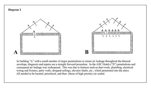
American Ski Company: Ice Dam Case StudyIntroduction & Air SealingIntroductionThe ProblemIce dam formation is one of the predominate problems for buildings in cold climates. The causes of such formations are often misunderstood by building owners and construction industry professionals alike. Because the heat-loss sources usually cannot be visually detected, solutions to the problem are more apt to be attempts at limiting damage from the symptoms, rather than preventing damage by eliminating the root causes of the ice dams. Excessive warming of snow-covered roof surfaces in sub-freezing weather is a prevalent cause of the ice dam phenomena which results in significant roof leaks. Systems for preventing the intrusion of water from ice dams into the building envelope (like installing waterproof membranes under the shingles) can be successful, but are often expensive and do not improve the energy performance of the structures. Repairing defects in the thermal envelope, the root cause of ice dams, always saves energy and, in addition to preventing roof leaks, addresses the hazards from falling ice and potential structural damage to the building. Typical Causes of the ProblemThe warming of snow-covered roof surfaces when outdoor temperatures are well below freezing is the prescription for ice dam formation. When melt water from warmed roofs runs down onto colder surfaces (such as overhanging soffits or well-insulated sections of roof), it re-freezes and forms ice. Where the snow pack ends, water doesn’t run off as in the summer, but is held by the snow pack like a sponge until it re-freezes. As this phenomenon occurs in a repeating cycle, the edge builds up and retains the water behind a dam of ice. When the water levels in these reservoirs get deep enough, the water runs up under the shingles and begins to leak into the building. If the volume of melt is too great and the ice dam overflows, the water running out of the snow pack forms potentially hazardous icicles. Typically, roof warming that leads to ice build up is caused by one, or a combination of, the following three variables:
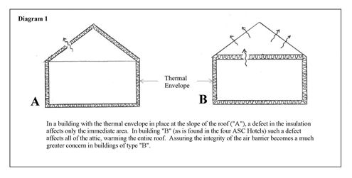
Inadequate R-values means that conductive losses through the building’s insulation are excessive. Minimum R-values are usually set by local code standards. Roof and attic standards are higher than those for walls because the snow pack on a roof provides some R-value and the higher roof insulation values maintain the point at which thaw can occur inside the thermal insulation rather than outside in the snow itself. These recommended insulation values typically are between 30 and 38 in northern New England, but are higher in climates where deeper snow is common. Missing insulation, gaps in batt insulation, or insulation that is too thin are common examples of inadequate R-value problems. As stated by Wayne Tobiasson, “The best way to stop icings at the eaves is to insulate the roof a reasonable amount for energy conservation reasons (R20 to R40 usually, depending on the situation)” [1] and, “good insulation and continuous air barriers between the living space and the attic are essential so as to minimize the passage of heat and warm air into the attic.” [3] Warm air leakage through penetrations into cathedral roof slopes will create melt in areas at the leakage site and in passages where the warm air flow makes its way (usually up) to the outside. In vented roofs this is usually in the vent chutes of the bay affected by the warm air leak. In vented attics, warm air leakage through penetrations in the attic floor through one or two locations can warm the entire roof surface. There are very few requirements for controlling air leakage unless a building owner is participating in one of the energy mortgage programs that establish a maximum air leakage rate. Most architects rely on specified vapor-control measures (vapor retarders) to double as air barriers, but vapor-control standards primarily deal with the permeance of materials, not moisture transported by air movement. Common problems like penetrations from mechanical equipment, interior structural members, interior partitions, recessed lights and fans, and vertical shafts for elevators or chimneys conduct heat much faster into roofs and attics than minor defects in insulation. Inadequate Ventilation means that there isn’t enough outdoor air coming into the roof vent passages or a ventilated attic to carry away the heat that escapes from the building. Even a perfect installation of insulation, vapor retarder, and air sealing materials will still allow some amount of heat to be lost from the conditioned building into the roof slopes or attics. Solar gain is another source of attic warming. Ventilation standards were originally developed to control moisture; however, ventilation standards have typically been adequate to supplement modern prescribed insulation levels so as to avoid ice dam problems. Blocked or missing inlet and outlet vents are common causes of inadequate cooling. It should be noted that improperly installed ductwork can contribute significantly to both the R-value and air leakage sources of the attic warming picture. Typical SolutionsAssuming that roof and attic cavities are large enough, it is relatively easy to add additional insulation when R-values are too low. In most cases, standard insulation and ventilation practices are installed in adequate quantities at the time of construction and these two variables can be ruled out as primary causes of attic warming. Once the building has been insulated and fitted with vent chutes, attic gable vents, and ridge venting following standard building practices, warm air leakage into the roof or attics is the most important problem to address. Flows of warm moist air into attics through relatively small openings can completely overpower very high insulation values. In most cases ventilation alone will not be able to carry away enough heat from significant air leakage sources because increasing the ventilation inlet and outlet areas (usually leading to depressurization) will “draw” more heated air from inside the upper (pressurized) floors of the heated building. Major air leakage sites, including ductwork and air handling equipment, must be sealed in order for ventilation to handle any remaining losses from minor air leakage and insulation defects. Once warm air leakage is under control, adding ventilation to meet normal standards usually can provide the additional cooling required to avoid ice dams in typical buildings. It should be noted that specific roof configurations or micro-climates can create conditions where ice can still form, even in well designed and constructed roofs; however, this is usually limited to specific problem locations and may not be of long enough duration to cause water leakage at the roof. In addition, while the buildings are intended to meet current insulation, roof/attic ventilation, and other environmental control and performance standards, the actual design and assembly of the components of the thermal envelope can still lead to ice dam problems. Specific Problems Encountered at the ASC HotelsIn general, the theoretical insulation values (R-values) used in the construction of the four hotels should be adequate unless snow buildup is deeper than normal. Specific locations have sub-standard insulation levels; but, as a rule, conductive losses are the least problematic of the three ice dam control (keeping the roof cool) mechanisms.
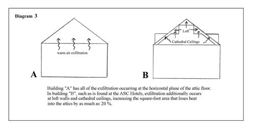
Warm air leakage into in the roof and attic spaces and inadequate ventilation are the most significant problems in these large buildings. Complicated construction details and mechanical penetrations provided many warm air leakage paths into the attics and roof slopes of these buildings. The types and methods of repair will be described in detail later in this report. Ventilation is compromised in a number of ways. The design of the buildings maximizes the number of tenable spaces with windows, even in the upper floors. By incorporating dormers and intersecting building segments, upper story and loft units have attractive balconies and windows that provide access to spectacular views. These architectural amenities, however, create numerous major and minor valleys, block air flow, and provide little space for roof and attic ventilation inlets along the soffits. The small areas that remain between the dormers and major valleys also concentrate the flow of any melt runoff into the small drainage outlets between them. To compound this problem, ventilation outlet areas, usually in the form of ridge vents, are either restricted or blocked by construction detailing, and are frequently covered by snow when they are needed the most. (see Ventilation Report) Specific Solutions for the ASC HotelsPreliminary inspections of the hotel attics indicated that the R-values were adequate; therefore, except in cases where the insulation was totally missing, adding more insulation was not a focus of this work. Infrared inspections by ASC (Moreau and Skroski) and FOAM-TECH personnel showed that significant air leakage was evident in all of the attics of the four hotels. This was supported by photos of snow melt patterns which showed the lower cathedral roofs and dormer roofs holding snow and ice, while the attic roofs above were bare. Ice formations were only on the colder roof surfaces below the attics, revealing that the lower slopes were performing, while the attics were not. The large volumes of ice also indicated that snow melt was from the larger surface areas of the attics. Experience with repairing ice dams and generally accepted building science principles indicate that, given adequate R-values and prescribed levels of ventilation, warm air leakage from the conditioned space into roof and attic spaces is the primary cause of ice dam problems. Preventing the warm air leakage into the attic spaces will then reduce attic warming and ice formation to manageable levels. In general, the prescription for a successful roof cross-section in buildings with this type of attic would be as follows:
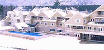
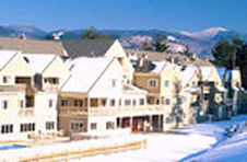
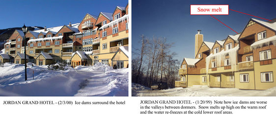
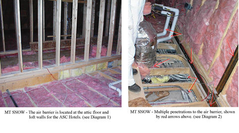
All of these types of penetrations and mechanical system problems were found in the ASC hotel attics. In addition, openings along party walls, at open floor perimeters under the lofts, and large chimney and duct chases were present. To reduce the impact of hundreds of locations of warm air leakage into these attics, FOAM-TECH used state of the art testing and temperature monitoring procedures in a phased approach to locate and prioritize the penetrations. The results of this testing were used to guide our crews in making the most cost-effective repairs possible. Using the test data and periodic quality assurance follow-up tests, these teams of technicians installed sealant and air barrier materials to eliminate a significant percentage of the worst problem areas. Ongoing temperature monitoring, in combination with infrared testing, was used to constantly assess the results of this work. The repair phase of the work was finished when the indoor and attic temperatures were effectively uncoupled, and the outdoor and attic temperatures were paralleling each other. An analysis of this temperature differential showed that the desired statistical relationships between the three temperature zones (conditioned space, attic/roof, and outdoors) had been achieved as a result of the repairs. This conclusion was corroborated when the repairs began to display a diminishing improvement in performance as the lower priority (smaller) leaks were sealed. As the attic temperatures were still above freezing, even though the data showed that the air leaks were substantially closed, the roof and attic ventilation systems were surveyed to determine why the remaining building losses were not being “flushed” by the cold air flow. As a result of this assessment, it was determined that the available ventilation did not meet the standards for attics and roof slopes in this climate, and that more ventilation would be required to handle the remaining building losses. To support this conclusion, two attics were tested to verify that additional ventilation was the final key to the success of the project. Ventilation was added to the worst (warmest) attic and one of the largest attics to provide data that allows us to model attic performance. The results of these experiments are found in the “Ventilation Report”. How We Became InvolvedFOAM-TECH has been involved in numerous ice dam prevention projects, including several at ski resort locations. Among these were projects at the Killington Ski Area. ASC, the owners of the Killington Grand Hotel, had experienced many “snow country” problems, and knew that installing measures to prevent roof melt leakage would only address some of their problems. Adding a waterproof membrane under the shingles and improving flashing details would limit the damage, but would not provide a solution to excessive heat loss, water entering through walls at lower levels, and damage from falling ice. All of these precautions would have been expensive and provided no guarantee that all of the problems would be eliminated. As a result, FOAM-TECH was contacted to price the complete removal of the existing insulation, the installation of air sealing foam over the entire attic floor, and the replacement of the existing insulation. This was a monumental task, encompassing nearly 200,000 square feet of attic surface and an excessive price tag of nearly $2,000,000. Our ApproachIn order to significantly reduce the cost and time that would be required to make these repairs, FOAM-TECH proposed to use the monitoring and test procedures mentioned above to locate and focus the work only in the worst heat loss areas. By locating and targeting the worst leakage areas in the attics, thousands of square feet of area that were performing at reasonable levels, as much as 75% of the attic and loft wall surface areas, could be left undisturbed. This approach relied on successive cycles of diagnostic testing and continuous temperature monitoring to determine when each attic was uncoupled from the inside conditioned space and that doing further repairs would no longer be cost-effective. This approach was successful in limiting the amount of repair work required and in determining that the building ventilation systems were inadequate. This could only be established once the air leakage had been reduced to manageable levels. Proper construction practices that meet ventilation standards normally allow for adequate air movement. Therefore, it wasn’t until it was known that repairs alone had not entirely eliminated the snow melt and ice formation that we questioned the ventilation system performance and proceeded to do an in-depth ventilation assessment. This research led to an understanding of the ventilation problems and revealed just how little of the required ventilation actually is available when it is needed. This data can serve as a foundation for the planning and installation of additional ventilation. As part of a ventilation upgrade, the attic temperature monitoring system would be available as a controller to operate powered attic ventilators so they would run only when needed. In addition, this system will serve to closely “watch” attic performance and automatically warn against future problems. Air Sealing ReportIntroductionThe following section of the report reviews and summarizes the results of H. C. Fennell, Inc.’s work for American Skiing Company (ASC) this past winter and spring (12/99 - 4/00). H. C. Fennell, Inc. has been contracted to solve the problem of the severe ice damming that occurs on the roofs of four of ASC's resort hotels. These ice dams form as a result of “warm roofs” that melt snow into water that then moves down slope and reforms as ice at the cold roof sections below. The ice damming and the consequent water leakage into the hotels (water trapped behind ice dams moves upward and under roof shingles and into the hotel) are severe in nature (see photos below). The problems are due to the obvious abundance of snow on the roofs (the hotels are located in the Green and White Mountains of Northern New England) and the fact that, prior to our repair work, there existed very serious compromises to the buildings’ thermal envelopes. The thermal envelope is located at the attic floor and up and over loft unit walls and ceilings, allowing warm air to move freely into the attics from the interior heated spaces. To further exacerbate the problem, it was discovered that the attic ventilation systems that are in place at the four hotels are inadequate. The presence and severity of this problem was established by observations made while in the attics performing repairs to the buildings’ thermal envelopes. It was then confirmed and expanded upon through detailed inspections of the existing ventilation.
The Problem: What Exactly Causes the Extensive Ice Dam Problems at the Hotels?It would be difficult to find buildings anywhere that posed as great a challenge as these four hotels did. The design and construction of the buildings resulted in a compromised and ineffective air barrier at the attic floors and loft walls. The hotels are very large in scale, ranging from 520 to 780 feet in total length. The diagrams that follow illustrate various aspects of the repair work challenge.
A situation that presented perhaps the single largest compromise to the air barrier was the existence in three of the hotels of a suspended ceiling over the center hallway that runs the length of the hotel. This occurred at Mt. Snow, Jordan Bowl, and Attitash. Suspended ceilings in and of themselves are very ineffective air barriers. The supposed air barrier in this location is actually about a foot and a half above the suspended ceiling (see photo below) and consists of friction-fit glass fiber batts fitted into the two-foot bays created by the bottom truss-chords. The batts are a very poor air barrier solution. This meant that warm air was easily leaking through and around the dropped ceiling and traveling along the entire underside of the insulation plane. It then migrates outward until it is able to find breaks or gaps in the batts that it can exploit to move up into the attic (see Diagram 4 below).
Here we present an overview of the procedures followed, techniques applied, and materials used to affect air barrier solutions. We also examine a few specific examples of the work. The list below specifies all of the air leakage problems encountered in the ASC Repair Work:
It may be helpful to understand the “philosophy” or “job #1” as it applies to air barrier work. In each section of the attic, there were multiple air barrier components “separated” by gaps that allowed varying amounts of warm air to leak into the space above. In some cases there might be sections of ceiling separated by open partition tops or chases at the ceiling plane of the rooms below, next to a loft unit or floored attic. It is our job to “connect the dots”, or in this case the air barriers. The process goes like this: Identify the possible air barrier components between the attic and the conditioned space. (Gypsum ceiling, plywood floor deck, masonry fire wall, structural member.) Select the available air barrier components that you think will be the easiest to connect to the next one, making sure they will ultimately form a continuous barrier from one boundary of the attic space to the other. In some cases this may include small components like the top plate of a partition or a beam, and in other cases it may be expanses of gypsum board ceiling or masonry firewall. Select the air barrier material to be used in “bridging” the gap. Gap sizes and labor and material costs are the most important. Other considerations include the vapor conductivity of the material (permeability – to dry or not), structural integrity (avoid building concealed traps), seal ability (sealants must adhere to each other), life expectancy, etc. Join the materials, changing planes as required, to connect from one air barrier material to the other. Batt insulation should not be included in the barrier. Test the total attic barrier to determine if any of the connections are incomplete, or if there are other leaks in the “assumed” existing air barrier materials. Repeat Process where needed. The Hallway Ceiling ProblemTo remedy the suspended ceiling problem that existed in three of the hotels (see Diagram 4), repair crews installed a new air barrier above the suspended ceiling. This air barrier was sealed to the I-beams that ran along both sides of the hallways in some areas, and to partition framing members in others. Spray foam and rigid foam board were used to seal below the I-beam to the top of the Corridor walls in this area, thus containing the warm air leakage above the dropped ceiling to within this now clearly defined cavity. Overview of Overall Project Repair Work
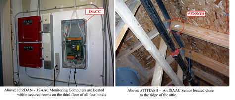
The effectiveness of this repair work, we needed information about pre-existing (baseline) and the continual, ongoing conditions in the attics. Ice damming is a phenomenon that can only occur if a certain differential in temperature exists between the exterior and the attic. This equation will be explored further in the Assessment section of this report, but here we need only know that since ice dams are a temperature-based phenomenon, we needed accurate and comprehensive temperature data to guide the repair work. By establishing a “base line” data set of attic temperatures before repair work began and then comparing it to an “after repair work” data set, we were able to assess the results of each phase of the repair work. This information is also provided in the Assessment section of the report that follows. The attic temperature data was also used to support the infrared scanning and other diagnostic tools that were being utilized in the field in order to make ongoing project management decisions. To accomplish this we installed an ISACC™ (Intelligent System for Automatic Communications and Control) System, a computer-based monitoring system, at each hotel. The ISACC unit allows for up to sixteen temperature sensors to be connected to it. We located one sensor at the outside of the building and the rest were arrayed throughout the attics (up to 15). These sensors then fed temperature readings to the ISACC, which stored the data and allowed us to dial-up via a modem and download the temperature data for ongoing review and analysis. To assure that a sensor located at the top of an attic at the ridge was adequate for determining conditions throughout the attic zone, we set up an experiment in one attic across the hotel’s cross-section. The results of this experiment concluded that a single sensor at the attic ridge line provided reasonably “averaged” readings that were sufficient for monitoring attic conditions. The value of the ISACC monitoring system in the overall success of this project cannot be overstated (see photos below).
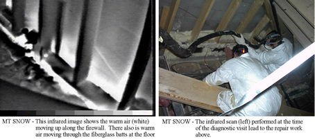
Other trends and conditions revealed by the data were: the affect of solar gain, the affect of snow covering the ridge vent (see “Ridge Vent Failure” section), the affect of micro-climate (i.e. hotel orientation and location at the mountain), the affect of fireplaces and chimneys, and the existence of overheated mechanical rooms on the third floor of the hotels (i.e. thermostats were set too high in theses rooms). All of these were contributing to attic temperatures and appropriate action, where possible, was taken. Another variable used in interpreting the ISACC data was the affect of wind speed on cooling attic temperatures. We compared wind speeds at Jordan Bowl provided by ASC to study this dynamic. A positive affect of wind on attic cooling can be shown, and while wind can't be counted on in a solution to warm attics, it does lend support for the application of power ventilation to produce and control the same affect. Diagnostic Test ProceduresAn invaluable tool used extensively in this project was infrared thermal scanning. Thermography allowed us to “see” the presence and amount of heat (see photo below), enabling us to pinpoint trouble spots in the buildings' air barriers. This tool was used during diagnostic testing to locate air leaks, categorize and prioritize them for repair work, and then to assess the quality of the repair work. This is the same equipment that was utilized by Moreau Electric Company, Inc., a consultant used by ASC prior to our involvement. In our repair work, it was used almost on a daily basis during this project. In the phased-approach that we used, where we systematically and cost-effectively eliminated air leaks until the attics reached a desired performance
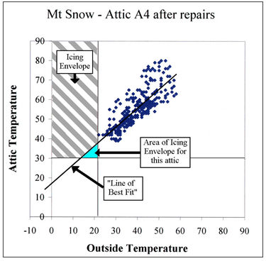
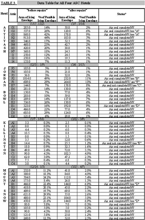
In that more extensive scenario repair work would have to be performed along the entire surface that might leak in order to ensure satisfactory results. Buildings such as these ASC Hotels have a vast area that would be suspect to air leakage and a blanket approach would have been exceedingly expensive. It would involve a massive amount of work unnecessary for the desired outcome of changing the attic-to-outside temperature differential only to the extent necessary for eliminating ice dams. This phased-approach allowed us to perform repair work of high-priority in the attics, and then step back and re-assess (from ISAAC data and a second round of diagnostic infrared scanning and observation) attic performance to decide if further repairs would be necessary. In the case of two hotels, Jordan Bowl and Mt. Snow, a second round of repair work was determined to be necessary. The following were also used to find air leaks and prioritize repairs. Snow melt-patterns were used on occasion for their ability to find roof hotspots. Each hotel's known water leakage areas were examined to determine if and when air leakage was a contributing factor. Crews were also trained and experienced at knowing how and where to look for air leakage. When large insulated areas were uncovered for access to air leaks, it was essential that technicians be able to make good field decisions about other potential trouble areas uncovered in the process. An example of a "Diagnostic Report" that was put together during diagnostic site visits to the hotels is included as Attachment F in this report. This Attachment also contains several photos that illustrate the kinds of problems found during diagnostics and served as a guide for repair technicians in their work. Under supervision and continual review, repair technicians applied the previously listed methods and materials to effect the best solution to the specific air leakage problems encountered. When infrared scanning, physical site-inspection, and the ISACC data all pointed to an effective air barrier being established, repair work was terminated. Assessment: How We Know if We Fixed the ProblemNote: The following information has been presented previously with the individual hotel reports that have been submitted (see Attachments A - D). It is presented here again for those who may only read this final ASC Project Report. How do we know when Ice Damming will no longer be a significant occurrence on the hotel roofs? Before we can determine if ice damming has been remedied, we need to have an understanding of the environmental conditions necessary for ice dam formation. From research we are able to establish a working equation for the conditions necessary for generating ice dams on un-insulated roofs. When the exterior temperature is 22 degrees F or less and attic temperature is above 30 degrees, then ice damming conditions exist[3]. Since the beginning of this project (12/99), we have been gathering temperature data via the ISACC Monitors that are installed in all four ASC Hotels. For this report the data has been separated into two datasets; one for the period before repair work commenced and a second for a period after repair work was completed. This data has been graphed for each attic of each hotel. An example of these graphs is displayed below to demonstrate how statistical methods were utilized in the assessment of attic repair work (see Graph A). The individual graphs are part of Attachments A - D, but included here is a table that summarizes the data for all four hotels (see Table 3).
The temperature parameters necessary for the formation of ice dams are placed on the graphs as an overlay and form the area known as the "Icing Envelope". We then graphed ISACC data in scatter-plots (see Graph A). From this we are able to determine when and how often attics are within the Icing Envelope. Further, we use the statistical method "Linear Regression" on the data and generate a "Line of Best Fit". The Line of Best Fit is computed by averaging the variance between exterior and attic temperatures. This is useful because it can be used as a measure of attic performance and as a predictor of the probability of ice dam formation on the respective attic's roof [3]. The Line of Best Fit is useful for predicting attic performance even when available temperature data is outside of the range necessary to form ice dams. This is possible when the "Coefficient of Determination", which is computed by the linear regression, is strong enough (meaning that there is enough data available to make a prediction and the data is statistically shown not to be significantly influenced by other variables). This test was applied to the data before using it for wider implications. Where the Line of Best Fit intersects the Icing Envelope, it forms the "Area of Icing Envelope" triangle. This important measure has been calculated for each attic, before and after repair work, and is our best measure of attic performance. To measure the area of the Icing Envelope we developed our graphs so that they had units of temperature as the scale for the x and y axis. (Please note this is a different scale than was used in the individual hotel reports, leading to different calculated values for the area of Icing Envelopes. This doesn't represent a change in the area of the Icing Envelope triangles.) We then computed the area of the Icing Envelope triangle for each attic. In the data table on the next page (see Table 3) we also converted this Icing Envelope area to a percentage of "Possible Icing Envelope" so that we had a useful benchmark for the comparison of attic performances. This Possible Icing Envelope is defined by the ice damming conditions equation with the limitations of negative 30 F as a low for the outside temperature and 70 F as a high for attic temperature. This forms a Possible Icing Envelope of 2080 (52 F x 40 F) and each individual attic's area of Icing Envelope is then divided into this to determine the percentage that the respective attic represents of the Possible Icing Envelope. One other data that is useful for our purposes is the "Slope" ("m") of the Line of Best Fit. The slope gives a visual representation of the relationship between the exterior temperature and the attic temperature. A slope of 1.00 (graphed as a Line of Best Fit with a 45 degree angle to the x and y axis) is the best possible and would indicate a perfect relationship between the two variables, meaning here that a change in exterior temperature is mirrored by an equally proportional change in attic temperature. Perfectly ventilated attics with no hotel air leakage would show this kind of slope. We used this measure in reviewing attic repairs and we are researching its wider implications for repair work assessment with the authors of this diagnostic approach. Another statistical phenomenon that we are watching to better understand how it can be used as a measure of attic performance is that of "lag time", which simply is the amount of time that it takes for attic temperature to track to that of the outside temperature as it rises and falls. When used with the area of the Icing Envelope, it appears that it may have significance as a measure of knowing when air barrier repair work has reached a certain level of completion.
“Air-seal complete” means that we have created an air barrier that is sufficient and cost-effective toward the goal of eliminating ice damming on the roof of the respective attic. Note that in all cases, due to poor existing ventilation and the further problem of snow on occasion closing down the entire ventilation system, additional ventilation needs to be installed in the attics (“NV” = Needs Ventilation work). Later in this report we present the results of the ventilation experiment that was successfully carried out at Jordan Bowl on Attic (F2). Because the additional ventilation worked so well at Jordan, which had a “% of Possible Icing Envelope” of 11% before ventilation, we believe that any attic that has this size Icing Envelope or less can be corrected with similar methods. The only attic that is worse than this measure is Attic F1, which is next to Attic F2 at Jordan Bowl. We have studied the conditions in this attic closely and are confident that F1 will also be moved out of the Icing Envelope with correct amounts of inlet and outlet ventilation. In the case of Killington, the Icing Envelopes are shown to increase in some cases, mostly in the B Attic section. However, the Icing Envelopes are extremely small for this hotel and the differences between “before” and “after” period Icing Envelopes are considered statistically insignificant (less than a 1% difference). Our remaining concern for Killington is that the duct-vent issue be addressed (see “E” below). “A” = In these two attics (G2 & G3) there exists over 50 feet of un-insulated and unsealed ductwork. “B” = This is a site where power ventilation has now been installed and information in the Ventilation section of this report shows dramatic improvement as a result. “C” = This attic is above the site of where extensive remodeling work took place after our repair work was completed and it is known that significant new air leaks reside there as a result. “D” = This attic is particularly problematic in that it is located above a loft unit and is also beside a firewall. This means that warm air from interconnected attics rises up into this attic and is then unable to dissipate due to the presence of the firewall and inadequate roof venting above. Infrared scans show the floor is effectively air sealed. The warm air that collects here needs to be ventilated from the building. “E” = This attic has a critical air leak within the ductwork that is open to the entire hotel lobby area below (four floors). The louvered vent that is a part of this ductwork has now been closed but has not been air-sealed because of fire safety concerns. Warm air easily passes through the vent here, even when the vent is closed, and affects the entire B section of the hotel attic. As a result the worst ice dams at Killington are found in this area. “F” = This attic is particularly problematic because it is located beside a firewall and has a minimal amount of existing ventilation. ConclusionsWe know empirically that the repair work has had a significant positive effect on the cooling of the attics and that our work has brought two of the three attic variables (R-value and air leakage) to acceptable levels. While the data shows very encouraging results, we have noted that in spite of this, many of the attics have not moved completely out of their respective Icing Envelopes and some ice is still forming on the hotel roofs. However, tests indicate that once adequate ventilation is in place, our air- sealing work will be able to have achieved the goal of the project. We have used established data collection and analysis procedures, confirmed by outside consultants. The “Ventilation Report” which follows will show how we have determined that the attics do not have adequate ventilation, and that the balance of the cooling required to prevent problematic ice dams can be provided by increasing ventilation. RecommendationsThere are some remaining details that might still be necessary even after ventilation is installed. These include such items as were outside of our original scope of work that have been reported in related correspondence or in the individual hotel reports (see Attachments A – D). The attic details that are affected by these problems are identified in the Data Table for All Four ASC Hotels (see Table 3) and include:
Related Information
| |||||||||||||||||||||||||||||
 |
|||||||||||||||||||||||||||||||