|
|||||||||||||||||||||||||||||||||||||||||||||||||||||||||||||||||||||||||||||||||||
|
|||||||||||||||||||||||||||||||||||||||||||||||||||||||||||||||||||||||||||||||||||
|
|
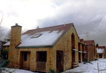
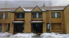
Case StudyRoof Ice Dam Remediation for Northeast Ski-Area CondominiumsPart IIby Henri C. Fennell ResultsPhase I DiagnosticsFour of the oldest units with full-time residents (non-rental units) were selected to maximize project access. The four dwellings comprised all of the units in one of the typical four-family clusters. The four-unit cluster chosen provided two "end units" and two "middle units" to evaluate and serve as baselines for comparison with other unmodified units. (The only other type of cluster layout was comprised of three similar units - two end units and one middle unit). Once the test units were established, an experienced local contractor was selected and the process was implemented. The video and photographic evidence was presented by the author to the owners, the contractor, the architect, and the property manager - hereinafter referred to as the team. From this review, the most severe areas of interior heat loss or roof surface warming were located. Architectural drawings were examined and plans were made for the contractor to develop access to inaccessible areas. The contractor then made inspection openings in soffits, chases, attics, and dropped ceiling areas to allow visual identification of the actual construction details at the areas of significant heat loss. These problem areas were organized into the following four categories:
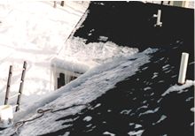
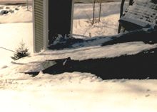
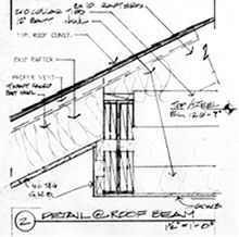
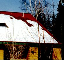
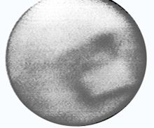
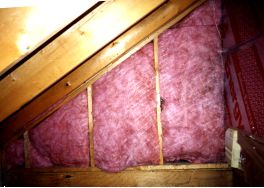
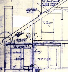
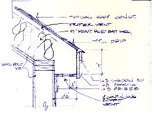
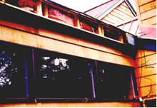
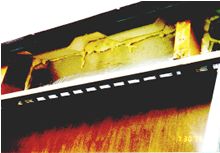
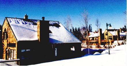
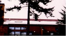
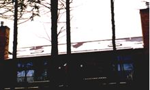
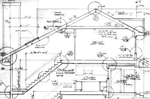
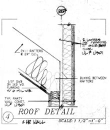
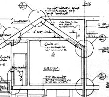
While remedying many of the energy conservation and freeze-up problems (Items 1 and 2 above) was included in the work and resulted in fuel savings and reduced repairs, only the ice dam formation causes (Items 3 and 4 above) will be addressed in this paper. Cathedral Roof Slope Warming – Problems Identified in Phase IIn this project, "cathedral" roofs are areas where both the inside and outside of a sloped roof are finished surfaces (no attic space). These areas were typically at the lowest roof elevation and always had attics above them. The cathedral roof construction, from the inside to the outside, consisted of gypsum board or horizontal tongue and groove wood paneling, 4 mil polyethylene vapor retarder, 2 x 12 wood rafters at 24" O.C., 9" un-faced batt insulation (R=30), continuous molded polystyrene vent chutes, plywood sheathing, and asphalt shingles on roof felt. The soffits were narrow in most locations and had continuous ventilation strips in the bottom trim. The ventilation design included a ventilated ridge cap. Most of the ice dams were located along the lower vented cathedral ceiling eaves and behind the zero-clearance fireplace boxes. Ice was concentrated at the valleys where the runoff from both roofs combines. In spite of the ice build-up and water infiltration, these lower roof areas were performing the best thermally. It was observed that the outside surfaces of the cathedral roof areas were generally cooler than the attic roofs above. This was indicated on the outside by snow and frost patterns. Typically, after light snow falls (6" or less) or on frosty spring or fall mornings, the upper attic roofs were melted bare. Under the same conditions the lower cathedral slopes were covered with snow or frost, showing only "spot" melt areas related to specific interior conditions. These patterns were constant from bottom to top on cathedral spans as long as twenty feet, stopping abruptly at a line where the vented attics began (see Detail / Photo Essay # 4). The snow "melt" water flowing down from the warmer attic roofs froze when it reached the cooler cathedral roof creating ice dam formations and water infiltration (leakage) damage. In similar unmodified units, the property managers were forced to remove snow from the entire roof area to stop leakage as the snow depths increased. This revealed ice build-up on the roof surface extending all the way up the roof from the eaves to the attic floor height, indicating that the entire cathedral roof surfaces, not just the eaves, were cool enough to re-freeze the melt water from the upper (attic) roof surfaces Interior infrared analysis of cathedral roof slope areas during the Phase I testing revealed the following:
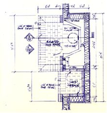
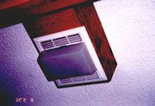
In the two end units there are bathrooms with knee walls and dropped ceilings. Between the knee walls and the dropped ceilings are short cathedral slopes. Melt patterns showed that this short cathedral area was performing better than the attic roofs around it, except in the bay with a recessed fan/light fixture.
Interior infrared analysis and physical inspections of these areas during the Phase I testing showed the following:
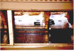
The 4" un-insulated flexible duct from the fan disrupted the insulation all the way up to the attic, and the warm room air flowed unrestricted up this duct against the roof sheathing. The long duct runs that vent to an exit point in the soffit on the other eave side of the building were exposed, thus dissipating any remaining heat into the attic space. The un-dampered termination cap was installed facing down in the eave soffit on the windward side of the building, encouraging the exhaust air to flow back up into the adjacent soffit vent strip and into the attic. This flow was visible during sub-zero weather. The light fixture had a high-wattage incandescent bulb that created a hot spot where there was little or no roof insulation. The infrared tests clearly showed the infiltration of cold air into the fixture, the outside melt pattern showed the fixture location and the warm air travel path in the roof’s vent space above the fan.
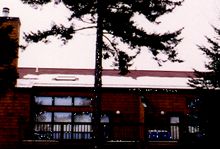
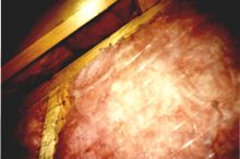
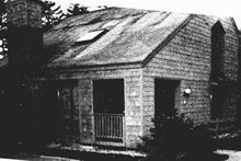
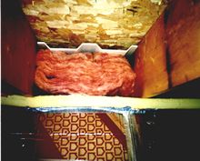
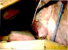
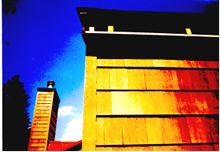
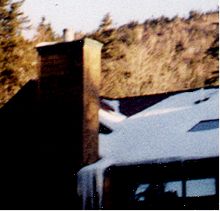
These attic-type roofs melted sooner than the surrounding cathedral slopes. Some were un-insulated or the insulation had fallen out of the stud bays. There was no air barrier in the plane of the knee walls between the floor and ceiling below. There were un-insulated recessed fixtures in the floor of this attic. While none of these surfaces were in the roof slopes themselves, they were assumed to be the causes of the warmed roof surfaces in these attics and in the cathedral slopes directly above them. Warmed ventilation air from the eave soffits below flowed through these attic spaces into the cathedral slope vent chutes starting at the tops of the knee walls. These interior "rafter tail" type conditions were not blocked below the vent chutes, allowing wind washing in the roof bays. Attic Roof Warming – Problems Identified in Phase IIn this project, attic warming was the largest source of melt water; and, as a result, heat loss to the attics was the most significant cause of ice dams. Warm air rising into the attic melts the snow and creates the bare roof areas as shown below.
Assuming a constant snow
depth, the volume of water generated for ice dam
formation is directly related to the surface area of
snow-covered roof that is melted by heat loss.
However, the physical size of the heat loss source
(i.e. the air-leakage hole size) is not necessarily
directly proportional to the roof area it can melt.
In the cathedral slopes, the area influenced by
specific air leakage sites was limited by the area
of the rafter bay that the leak was in, and the
volume of air that could flow out of the leakage
area through the ventilation chute or space. In the
case of the attic, a relatively small number of
square feet of air-leakage area (hole or penetration
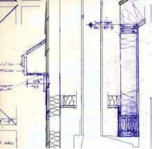
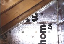
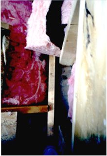
size) could allow the The attic construction, from the inside (below the ceiling) to the outside, was as follows: gypsum board, 4-mil polyethylene vapor retarder in the bedroom ceiling areas (not in boxed chases or dropped ceilings), 1 x 3 strapping, 2 x 8 wood ceiling joists - 24" O.C., a single 9" layer (R=30) or two layers, one of 6" and one of 3.5" unfaced batt insulation (total R=30). (Note: The second layer of batt insulation was turned across the framing and stopped at the intersection with the rafters, several feet short of the first layer (R=19) which went to the edge of the ceiling bays where they met the slope insulation). The ridge had a continuous vent. There was no ice formation observed on the upper attic roofs. Soon after a snow or frost event had occurred, a few hot spots would melt above specific areas such as the bathroom vents and the party walls then, the entire roof would melt clear over the attics of all four units. The combined losses from the sources listed below resulted in attic temperatures as high as 55 degrees (Fahrenheit) when outside temperatures were below 10 degrees F. Infrared analysis inside the attics during the Phase I testing showed warm air leakage into the attics from numerous sources as well as reduced R-values in the loose-fill fiberglass and batt insulation (4):
Phase I RepairsBased on a report of the results of the non-destructive and destructive test procedures, the team reviewed the problems and agreed to make the following repairs: Cathedral Roof Slope Warming – Phase I Repair Methods
Attic Roof Warming – Phase I Repair MethodsInsulated attic hatches with gaskets and draw-down latches were installed. In the flat ceilings of the attic, air sealing was done at all accessible penetrations under the batt insulation. The air barrier and insulation were extended into the party walls. Gaps in the batt insulation were to be filled with loose-fill insulation. An additional layer of loose fill insulation or a continuous vapor-permeable air barrier film was to be installed on top of the batts to reduce convection in the batts. The top of the insulated metal furnace flue was sealed to prevent the heat from flowing into the roof slope vent spaces.
| |||||||||||||||||||||||||||||||||||||||||||||||||||||||||||||||||||||||||||||||||
 |
|||||||||||||||||||||||||||||||||||||||||||||||||||||||||||||||||||||||||||||||||||