|
|||||||||||||||||||||||||||||||||||||||||||||||||||||||||||||||||||||||||||||||||||||||||||||||||||||||||||
|
|||||||||||||||||||||||||||||||||||||||||||||||||||||||||||||||||||||||||||||||||||||||||||||||||||||||||||
|
|
The Use of Polyurethane Foam Technology in HistoricRenovation and Remediation WorkCase StudiesAllen Memorial Art MuseumOberlin College 1998 Restoration – Architect: James Montalto; Engineer: Landmark Facilities Group; General Contractor: T. J. Hume Company, Inc.
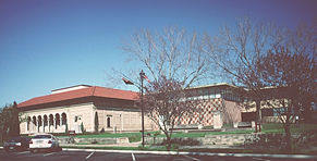
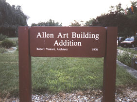
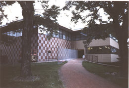
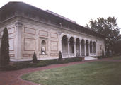
Founded in 1917, the Allen Memorial Art Museum (AMAM) is now ranked among the finest college or university collections in the nation, and is one of the greatest cultural assets of Oberlin College. The comprehensive collection, which contains over 11,000 works that span the entire history of art, is particularly strong in the areas of 17th-century Dutch and Flemish painting, European art of the late 19th and early 20th centuries, contemporary American art, and Old Master and Japanese prints. The buildings that house the Allen Memorial Art Museum’s collection, and the college art department, are no less engaging than the works of art within. The complex of buildings designed by Cass Gilbert in 1917 represents an eclectic dialogue between Tuscan Renaissance and Midwestern vernacular architectural styles. The addition to the Allen Memorial Art Museum by Robert Venturi, Denise Scott Brown, and Associates is one of the earliest and finest examples of postmodern architecture in the United States. In its complex dialogue with the Gilbert building and its innovative use of ornamentation, this building was pivotal in the new appreciation of architectural context and symbol that developed during the 1970s and '80s. (Allen Memorial Art Museum Web Site)
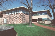
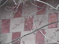
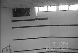
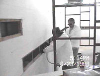
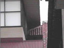
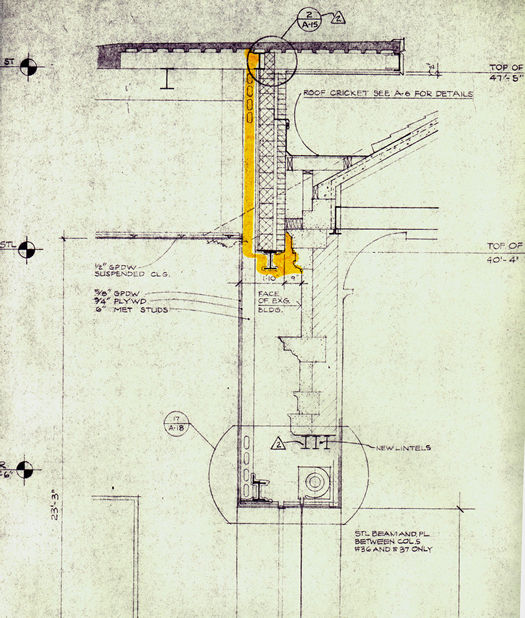
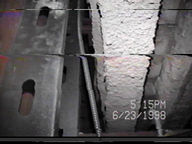
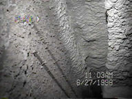
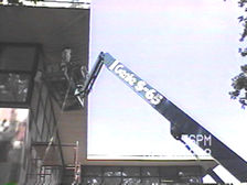
Polyurethane foams were used in the Venturi Gallery Addition portion of the project to stop problematic moisture migration through the exterior walls. This moisture was causing staining and spalling of the checkerboard cut-stone façade.
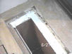
Improved climate control was also a goal of this project. A medium density (2.5 pound per cubic foot), zero ozone depletion potential, closed-cell foam was introduced into the 8" cavity (R=60, perm. <.25) using an injection method. Narrow strips of the inside sheathing and the window shelf were opened to provide access for filling the cavity between the interior sheathing and the existing high-density batt insulation. This technique avoided the need to remove the entire interior sheathing surface.
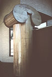
The cavities were injected in lifts up to each successive slot and then closed with the original cut-outs. This work included filling the small 1 1⁄2" space (R=10, perm.<1) between the pilasters and the interior sheathing.
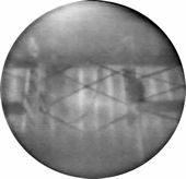
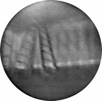
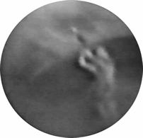
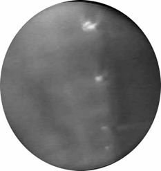
Infrared thermography was utilized to assure complete cavity fill.
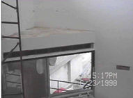
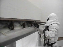
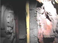
Incidental open areas in the gallery, such as the two-foot deep shelf cavity above the recessed entry of the building, were sprayed with 3" of closed-cell foam (R=21, perm. <1). This typically occurred where the cavities were too large to fill or when opening the cavity provided access for other work
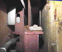
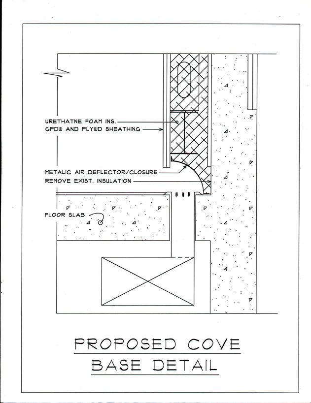
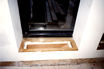
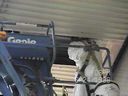
The original heating and cooling distribution system used outlets along the bottom of the wall and in the window sills. The wall framing was supported by a beam just above the wall-base registers. This system was open to the wall cavity, creating a convection flow of conditioned air inside the wall against the masonry. A light gauge aluminum form was installed to create a diverter for the air flow and to serve as a stop for the foam. The injected foam filled around this form, providing permanent support for the diverter, with enough space behind it to allow adequate R-value and moisture control.
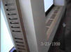
At the window sills, a plywood form was temporarily braced in position to extend the floor supply ducts up to the sill register. This was held to the inside to assure adequate room for foam to isolate the masonry from the air flow. Foam was injected around this form to provide permanent support for the air passage.
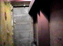
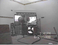
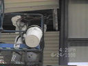
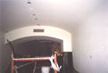
The security roll-up door offered another challenge for this retrofit work. The wall cavity at the intersection of the two buildings was not sealed or insulated where a door had been cut out between the old and new buildings. Injecting this cavity as it existed would have filled the operator and leaked out of the sliding door track. A form was installed on the side of the doorway from the dropped-ceiling above to protect the hardware before the cavity was filled. This door was kept closed during the renovations and the room was depressurized during the work to keep dust and vapors from entering the rest of the museum which was still in operation.
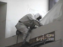
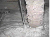
The tops of the walls above the dropped ceiling areas were insulated from the inside with 3" of spray foam (R=21, perm.<.70) applied directly onto the open wall surface. Visual inspection and frequent gauging of the foam thickness during the work were the primary methods utilized for quality assurance in this area.
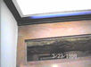
Air sealant was utilized at the intersection of the two buildings
.
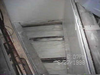
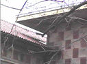
The roof framing cantilevers out to carry the soffit along the perimeter at the top of the wall. This area was essentially open to the outside soffit, and the existing insulation batts displayed the effects of moisture migration. The perimeter was air sealed from the outside through open sections of the soffit.
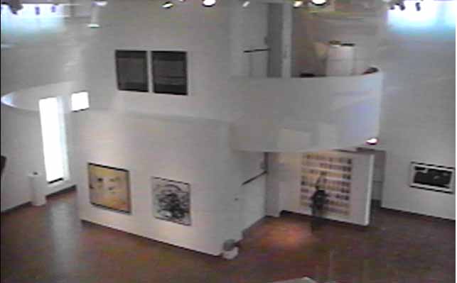
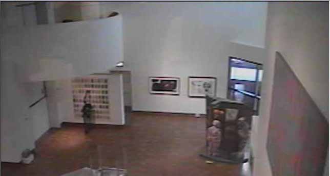
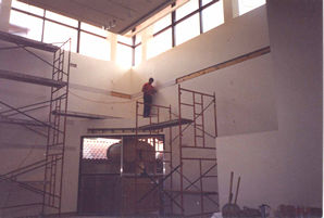
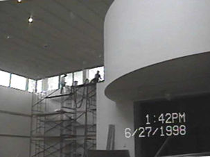
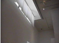
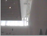
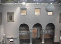
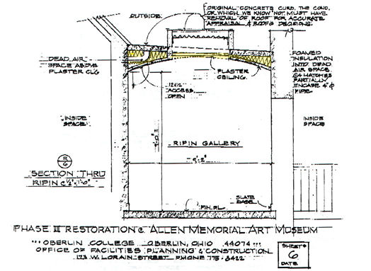
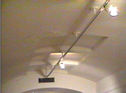
Polyurethane foams were also used in the Ripin Gallery in the Allen Memorial section of the building to stop energy loss and condensation in the exterior vaulted plaster ceiling cavity.
Damage from this source was occurring on the ceilings. Blooms in the plaster from water infiltration caused by condensation were evident in a number of places in the ceiling. Improved climate control was also a goal of this project. The same medium density foam (2.5 pound per cubic foot) closed-cell foam was introduced into the vaulted ceiling cavity (R=42 to R=160, perm<.5) using the injection method. 4" holes were drilled through the wire lath plaster and at the apex of the vault and along the skylight openings to provide access for filling the ceiling cavities. The deep sides of the vaults were filled first, then the more uniform center area was filled progressively from arch to arch. Infrared thermography was utilized to guide the technicians and to confirm the cavity was full.
Continue on to Vermont History Center | |||||||||||||||||||||||||||||||||||||||||||||||||||||||||||||||||||||||||||||||||||||||||||||||||||||||||
 |
|||||||||||||||||||||||||||||||||||||||||||||||||||||||||||||||||||||||||||||||||||||||||||||||||||||||||||