|
||||||||||||||||||||||||||||||||||||||||||||||||||||||||||||||||||||||||||||||||||||||||||||||||||||||||||||
|
||||||||||||||||||||||||||||||||||||||||||||||||||||||||||||||||||||||||||||||||||||||||||||||||||||||||||||
|
|
The Use of Polyurethane Foam Technology in Historic Renovation and Remediation Work Case Studies Vermont History Center
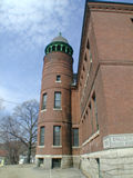
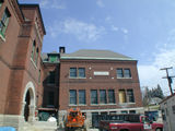
Vermont History Center - Spaulding Graded School 2001 – 2002 Renovation – Architect: Black River The Vermont Historical Society is in the process of converting the Spaulding Graded School in Barre into the new Vermont History Center which will house its research library, collections storage, exhibits, education facilities, and offices. The Vermont History Center is scheduled to open June 1, 2002. On September 14, 2000, the Society purchased the 1891/92 Richardsonian Romanesque school building (with its 1914 annex) and began the renovation of the school for use by the Society as a "history center." The school will add more than 60,000 square feet to the Society's current 14,000 square feet of operating space. The center will:
When the new library opens it will occupy 7,500 square feet on the second floor of the Vermont History Center, an increase of almost three times the size of the current library. The stacks will remain open as in the old building, but staff work areas will be separated from public spaces. Special air conditioning and humidification systems will work to preserve the collections. There will be separate rooms for microfilm readers, computerized databases, and maps and photographs. The Vermont History Center will also include classrooms, an auditorium, display galleries, and storage for library and museum collections (Vermont Historical Society Web Site).
The thermal envelope of this large building consists of many types of wall and roof configurations. A number of polyurethane foam formulations and installation techniques were used in this project to provide:
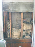
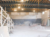
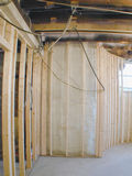
In the original 1891 section of the building, the exterior walls were comprised of brick with wood-framed stud walls inside on the upper floors. The 8"cavities are separated from the masonry by an air space and exterior diagonal wood sheathing. Most of the cavities have intermediate back-plastering near the outside of the wall.
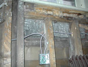
These closed cavities and the window-weight pockets were injected with less expensive open-cell polyurethane foam (R=30) due to the large cavity size. The insulation was injected through small holes drilled in the lath and plaster until an elevation at the top floor was reached where the wall could be topped off from the attic. Depressurized infrared quality assurance testing was used to locate blocking or other voids during the installation. Some wall cavities had to be opened up in the 1891 section. This occurred where the blackboards were removed to restore the original plaster finish, the wainscoting was removed to make mechanical installations, or where rubble or existing insulation had to be removed.
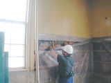
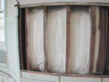
These bays were insulated with approximately 6" of open-cell spray
formulation (R=20) or a 3" layer of closed-cell polyurethane foam (R=21), depending on project sequencing. To complete the thermal envelope at the intermediate levels in this section, the perimeter between the floor joists was sprayed with 3" of closed-cell polyurethane foam (R=21) when open floors or ceilings provided access. Bays closed to spray application by the location of the first floor joist were filled with open-cell polyurethane foam from above or below; again, depending on the available access
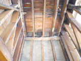
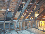
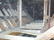
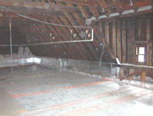
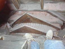
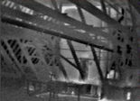
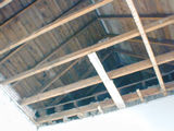
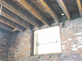
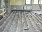
In the 1914 addition or annex wing, the exterior masonry walls on the upper floors were solid brick with the plaster and finish trim applied directly onto the brick. Much of this section of the building is planned as expansion space for the History Center, and no insulation was installed on the exterior masonry walls at this time, except around the outside of the new elevator shaft. This new concrete block shaft was built entirely inside the brick structure, spaced about a foot away from the outer wall. Prior to closing in the block shaft, the outside wall was sprayed with approximately 2 3⁄4" of closed-cell polyurethane foam (R= 19). Because the monolithic coating was bonded to the outside masonry, this protected application saved the cost of installing a stud wall around the outside of the elevator shaft. Long-range plans for the rest of the 1914 addition include the addition of stud walls, spray-applied foam on the masonry, and new interior finishes. The original 1891 building has a huge attic with some existing ventilation. The attic floor had an average of 4" of cellulose and Rockwool insulation (R= 15) in 2X8 joists. The majority of the floor area was sheathed with diagonal wood sheathing boards. There was no vapor retarder on the warm side of this thermal envelope and the lath and plaster or beaded board ceilings were the only existing air-barrier materials.
To address the thermal envelope correctly would require the removal of
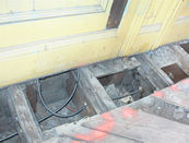
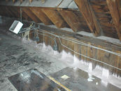
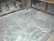
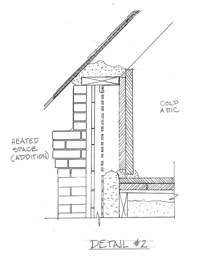
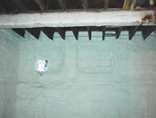
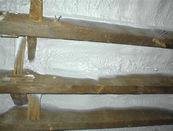
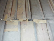
the floor boards and the existing insulation. After the ceiling had been cleaned out, and spray-applied foam air/vapor barrier had been installed on the warm side of the ceiling, new insulation and floor sheathing would be required. A more efficient plan was developed. The existing floor sheathing and insulation were kept in place, except over the demising walls around the climate-controlled spaces below. Narrow slots were created in the attic floor over the demising walls to allow a “connection” from the air/vapor barrier on top of the floor boards down to the top-plates of the boundary partitions below. The top of the floor was then covered with a 3" layer of rated, foil-faced, rigid polyurethane foam board (R=27) protected with walkways in areas where normal limited access would be required. It was determined that this R-value for the rigid foam was adequate to keep the dew point out of the existing insulation on the warm side of the foam panels. The layers of the sheet insulation were staggered and the top sealed with foil tape. Foam sealant was used at the perimeter, at small areas with complex framing or mechanical systems, and at changes of plane. This treatment extended up and over the knee walls where the 1917 annex was higher than the attic.
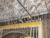
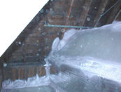
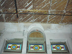
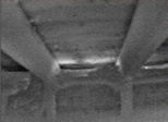
In the small dormers over the arched windows, the curved plaster ceilings were cleaned off and sprayed with 4" (R=30) of closed-cell polyurethane foam.
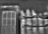
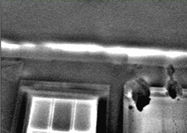
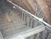
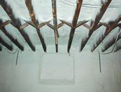
Infrared quality assurance testing was used to locate any remaining warm air leakage into the attic spaces after the foam sealant application. Penetrations around new mechanical installations and several other warm-air leakage paths were located during this process.
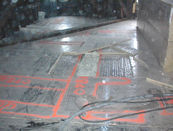
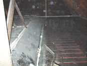
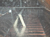
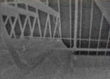
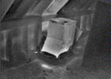
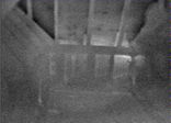
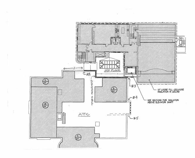
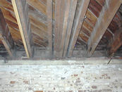
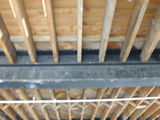
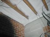
These included the original ventilation shaft (approx. 6" by 12") which had been torn down to just below the roof level and left with an open-top in the attic. This was discovered during the infrared testing and then determined to be a significant source of attic warming. The same type of rigid polyurethane foam board (R=11) was installed on the sides of the masonry shaft to prevent radiant heat loss through the sides of the shaft into the cold attic. Rigid foam panels were also installed and sealed over the top of the open shaft to stop warm-air flow due to the four-storey stack effect. Another complex problem was identified during the testing. A warm-air bypass around the attic floor envelope was identified in the brick cavity where the two wings of the building come together.
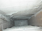
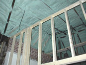
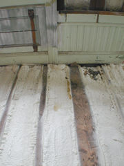
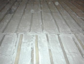
In this area, the brick cavity in the common wall between the original 1891 section and the 1914 annex are warmed by the heated space where this is an interior wall on the floors below. This warm air bypasses the thermal envelope at the attic floor and flows up into the attic at the two ends (locations 2 & 3 on the plan) of the overlap between the two buildings. The source of the heat is likely to be conduction through the interior brick walls and warm air leakage at any interior rough openings or mechanical penetrations on the floors below. Air sealing at the top of the brick cavity in the attic is underway using a combination of foil-faced rigid foam board and foam sealant. In the 1917 annex and the 3rd floor connector, the flat and sloped roof areas were generally un-vent able given the existing building elements. This thermal envelope problem was addressed by spraying 4" of closed-cell polyurethane (R=30, perm. <1) onto the underside of the roof sheathing from below. This approach eliminated the need to retrofit ventilation systems on top of the existing roof or to provide more space for insulation within the roof framing. It also avoided changes to the exterior trim detailing.
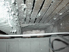
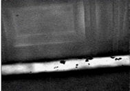
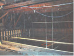
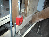
The masonry exterior walls in the basements of both the 1891 and 1914 wings of the building were sprayed with 3⁄4" of closed-cell polyurethane foam (R=5, perm. <1 due to high in-place density). The rim areas between the floor joists were essentially an extension of the basement walls and were also sprayed with closed-cell polyurethane foam.
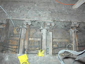
Interior stud walls for the mechanical systems and interior finishes were built after the foam application. The basement work included spraying over blocked-up windows and the underside of the exposed granite slabs in the two recessed entry stairways. Isolating the interior climate-controlled spaces in both sections of the building utilized spray-applied polyurethane foam as both an air-sealant and a vapor-control measure on the floors and floor perimeters. Closed-cell polyurethane foam was applied to the demising floor and joist perimeter surfaces in a 3⁄4" thickness, the amount specified to maintain the required temperatures and prevent moisture migration and airborne moisture transport between the conditioned and unconditioned spaces. Some floors were sprayed from below. Others with historic steel panel ceilings were isolated from above.
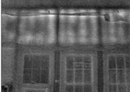
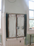
Vapor-retarder film was installed on new or renovated interior partitions. Vapor-retarder paint was used for the existing interior walls. In some of the climate-controlled rooms, the exterior windows were to be eliminated as sources of natural light and climate-control losses. On the upper levels, these windows were coated with a release agent, painted black, or replaced with spandrel glass; they will be sprayed with R=21 closed-cell polyurethane foam to maintain the original layout on the outside façade. This tactic was developed to allow the widow to be replaced. Continue on to Currier Gallery of Art
| ||||||||||||||||||||||||||||||||||||||||||||||||||||||||||||||||||||||||||||||||||||||||||||||||||||||||||
 |
||||||||||||||||||||||||||||||||||||||||||||||||||||||||||||||||||||||||||||||||||||||||||||||||||||||||||||