|
|||||||||||||||||||||||||||||||||
|
|||||||||||||||||||||||||||||||||
|
|
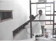
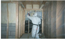
The Use of Polyurethane Foam Technology in Historic Renovation and Remediation WorkApplicationsVI. How are polyurethane foams processed on-site?Following is a description of the three on-site processing techniques for walls, roofs, and floors utilized in the case studies below: A. Techniques1. Injected, poured, blown-in, or foamed-in-place (FIP)This application technique is known by several names; basically, it involves injecting a relatively slow, pre-expanded foam system into a closed cavity. The foam reacts, expands again, and solidifies in the cavity within a few minutes. The process generates pressure, heat, and vapors. The result is a rigid, bonded product which fills the entire void. Properly executed, this ensures a thorough fill and complete bonding to the substrates. This requires a certain installation technique (small lifts and/or bracing), and fastening of the cavity surfaces in applications where pressure from the expanding foam may distort the finishes. The heat of the chemical reaction (240 degrees) is useful for quality assurance testing using an infrared camera to verify a complete fill free of voids. This installation approach requires that the area be warm (usually a minimum of 40 degrees F) before, during, and after the processing and curing periods (24 to 48 hours). The vapors require proper ventilation or personal respiration equipment to be utilized.
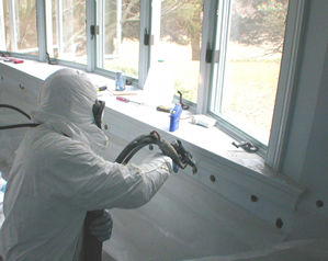
Comments: Injecting a closed cavity creates little waste, requires less masking than spray applications, and has minimal personal health issues (airborne particles) for the applicator. A clean, dry surface will maximize adhesion or bonding. 2. Spray-applied or sprayed-onThis application involves spraying a hot, fast, atomized foam system onto an open surface (like spray painting). The foam reacts, expands, and solidifies on the surface in seconds. This process generates heat, airborne particles, and vapors. The result is a rigid, bonded product which covers the exposed surface in a continuous coating. The rapid expansion requires a proper installation technique to make the coating as even as possible; however, the finish will never be perfectly “flat”. For this reason it is typical to spray-apply an “average thickness” which allows for a certain “plus or minus” tolerance. Alternately, a “minimum thickness” may be specified. The speed and heat of the chemical reaction also requires that the substrate and ambient temperatures be warm before, during, and after the process to prevent thermal shocking of the finished product during the processing and curing periods. Various chemical formulations have different temperature requirements, and the foam system must be appropriately chosen for the specific project conditions. Chemical systems are available for applications as severe as the frozen earth project at Boston’s “Big Dig”. The particles and vapors require proper ventilation or personal respiration equipment to be utilized. Masking or protecting finishes from over-spray is required as well.
Comments: The spray operation allows the installation to be a specified R-value in a cavity that is too large for injection due to practical considerations. If over-spray is not an issue, this technique has the highest productivity and usually the lower per-unit cost. 3. SealantThis application involves dispensing a medium-fast, pre-expanded foam system onto an open surface or into narrow cracks. This process is not atomized as much as a spray system; therefore, the pattern created is “courser”, but can be varied from a caulk-type bead to a broader fan configuration. The foam reacts, expands (low or high-expansion systems are available), and solidifies on or between the substrate surfaces in seconds. The process generates heat, fewer and larger airborne particles than spray applications, and vapors. The result is a rigid, bonded, product which covers small areas of exposed surface or expands to fill narrow cracks. The expansion requires a proper installation technique to fill a crack level with the plane of the surfaces being sealed; however, the finish will never be perfectly “flat”. Caution and/or bracing may be required in applications involving window jambs where pressure from the expanding foam may distort the trim if precautionary measures are not taken. This technique requires that the area be warm during the processing and curing periods to assure the quality of the finished product. Sealant is normally processed in small volumes, and while the vapors may still require ventilation, personal respiration equipment typically is not required. Masking areas which have permanent finishes, and trimming of excess material which expands out of the narrow cavity, may be required.
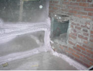
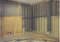
Comments: Foam sealant is usually used for detail work in small areas; therefore, the equipment output and the related productivity is much lower than with the injection or spray methods. Truck-mounted and small-scale portable equipment are available for this technique. B. Applications1. Walls
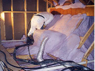
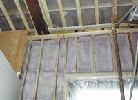
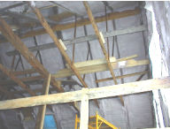
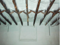
2. Flat ceilings and roof slopes
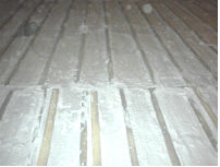
3. Floors
C. SequencingProject sequencing is generally project dependent, but typically follows normal construction practices. Project sequencing and preparation for the various installation techniques are too numerous and extensive for this discussion. Information is available on line at: D. Architectural SpecificationsSample architectural specifications (Section 7) are available on line at: Continue on to Allen Memorial Art Museum | |||||||||||||||||||||||||||||||
 |
|||||||||||||||||||||||||||||||||